Preferred Orientation in Cryo-EM: Causes, Sample Preparation, and Solutions
Preferred orientation occurs when particles in vitreous ice occupy a limited set of views instead of sampling a broad angular distribution. In single-particle cryo-EM, that imbalance can leave important directions underrepresented, reduce directional information, and hinder three-dimensional reconstruction. The practical response depends on why the particles favor those views and how the sample responds to changes in chemistry, grid support, vitrification, and data collection.
A useful troubleshooting plan separates interventions that reduce particle interactions with the air-water interface from those that alter the interface or compensate during data collection. The options are complementary, and several may need to be tested together for a specific target.
Preferred Orientation in Cryo-EM
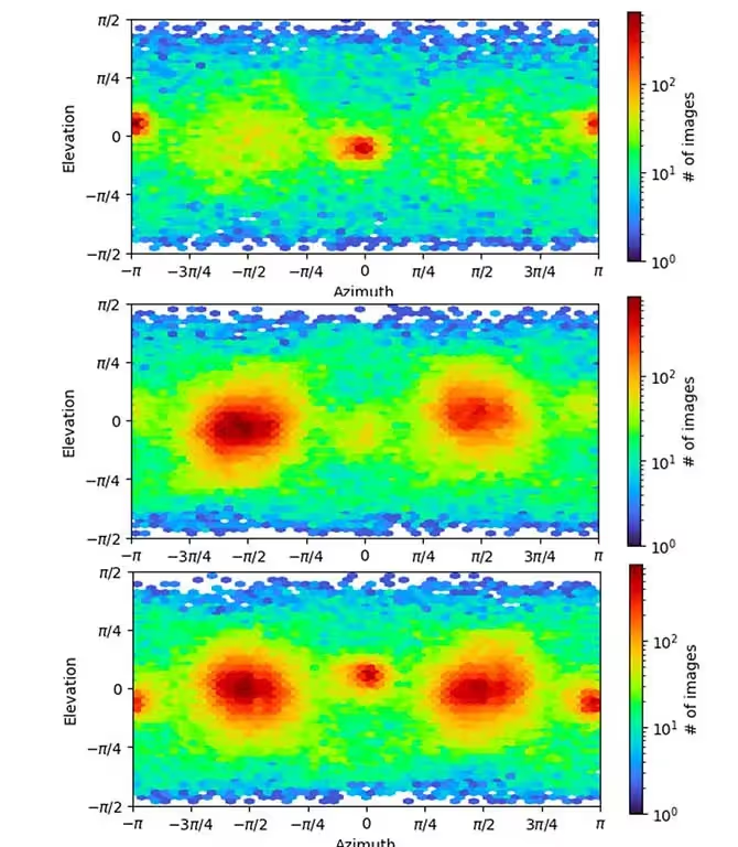
Single-particle analysis combines two-dimensional projections of many nominally identical particles to estimate a three-dimensional density map. A reconstruction benefits from particles that represent the necessary angular views. If most particles adopt the same face-on, side-on, or otherwise restricted orientations, the data can contain a gap in angular coverage. The resulting map may show anisotropic detail or may not support a reliable three-dimensional reconstruction [1, 4].
Preferred orientation meaning
In this context, preferred orientation means that particles are observed in a limited number of unique views. The related phrase orientation bias describes the same practical problem: some projection directions are sampled much more strongly than others. Molecular shape can contribute. Rod-like and disc-like particles, for example, often favor orientations with their long axes parallel to the grid plane. Surface chemistry and interactions with the air-water interface can also dominate particle behavior.
What Causes Preferred Orientation in Cryo-EM?
Protein particles can diffuse through the thin aqueous film and encounter the air-water interface many times during conventional blot-and-plunge preparation. Hydrophobic or otherwise surface-active regions may associate with that interface. Adsorption can constrain particle orientation and may also contribute to deformation, partial denaturation, or complex dissociation [1, 2].
Project observations compiled across nearly two years found that fewer than 8 percent of samples moved from initial vitrification to a full three-dimensional reconstruction at 3.5 angstroms or better within two weeks. Preferred orientation was the most frequent recorded hurdle at 29.1 percent, followed by instability at 21.5 percent and heterogeneity at 16.5 percent. Particle size, flexibility, low concentration, and aggregation accounted for the remaining recorded challenges. These observations describe that project set and should not be treated as universal rates.

How the Air-Water Interface Affects Particle Orientation
The air-water interface is the boundary between the aqueous sample film and air. In conventional preparation, several microliters of sample are applied to a grid, excess liquid is blotted, and the grid is plunged into cryogen. The interval between deposition and vitrification is on the order of seconds. During that period, a particle can interact with the interface hundreds to thousands of times according to the workflow observations summarized here.
Cryo-electron tomography studies have shown that particles commonly absorb at one or both air-water interfaces in vitrified films [1]. Absorption may produce a restricted orientation ensemble. It can also expose sensitive regions of a protein or complex to conditions that alter structure [2]. This mechanism is why some interventions focus on reducing the time available for diffusion, changing protein-interface interactions, or introducing a physical support.
Cryo-EM Vitrification and Preferred Orientation
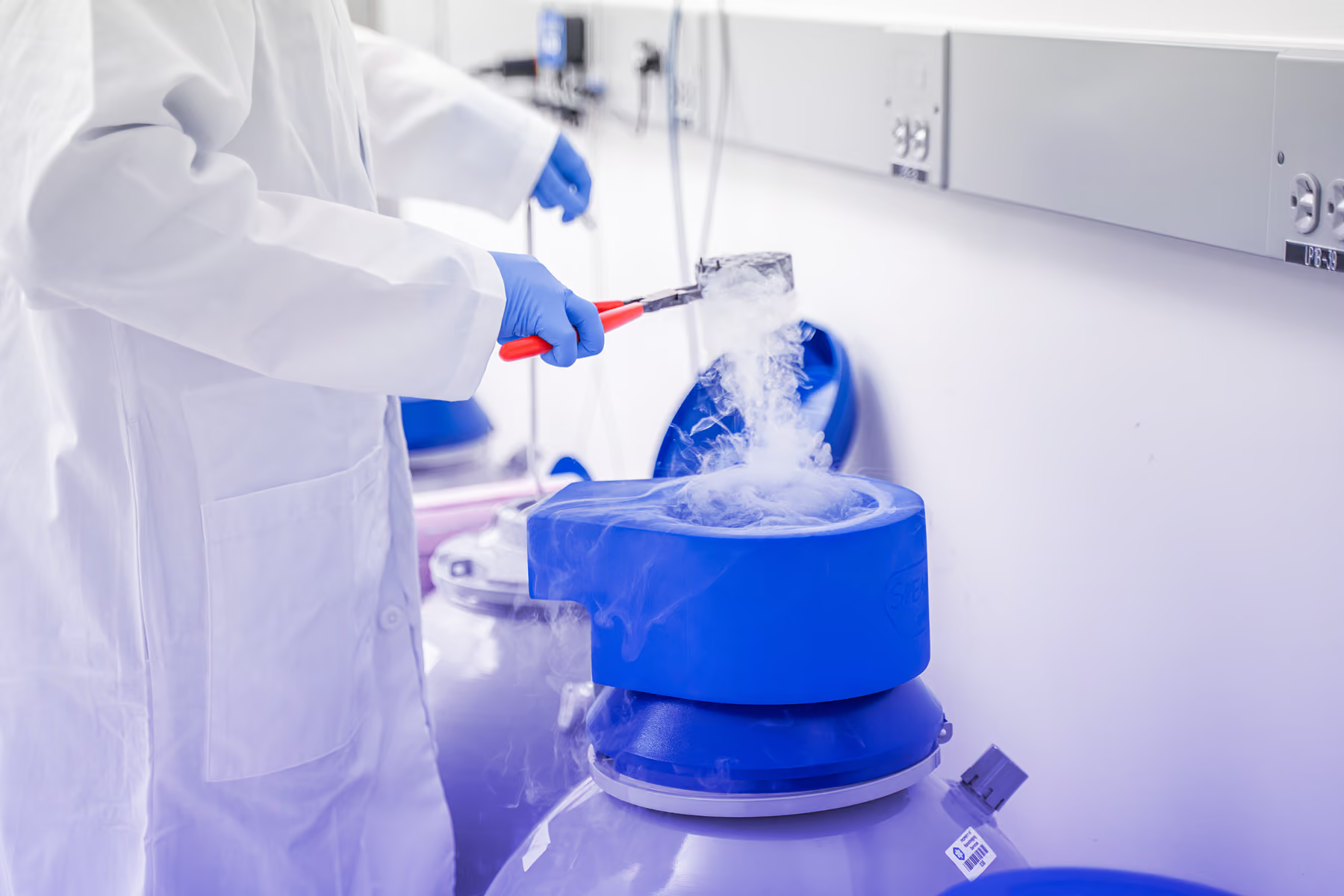
A conventional Vitrobot blot-and-plunge cycle leaves an interval of seconds between sample deposition and vitrification. The SPT Labtech chameleon sprays sample onto a self-wicking grid while the grid moves toward ethane, reducing the deposition-to-vitrification interval to a few hundred milliseconds in the workflow evaluated here. Faster preparation may reduce the opportunity for particles to encounter and equilibrate at the air-water interface, although the outcome remains sample-dependent.
In a beta-amylase evaluation, chameleon-prepared grids showed a broader view distribution and supported a higher-quality map than grids prepared with the conventional Vitrobot workflow. This result supports rapid vitrification as a testable intervention for that sample rather than a general guarantee for other targets.
Cryo-EM Preferred Orientation Solutions
Mitigation strategies fall into three practical groups: reduce or alter protein interactions with the air-water interface, change the physical surface encountered by the particles, or collect data in a way that recovers underrepresented views. A sequence of small, controlled tests can help distinguish among these mechanisms.
Detergents and additives
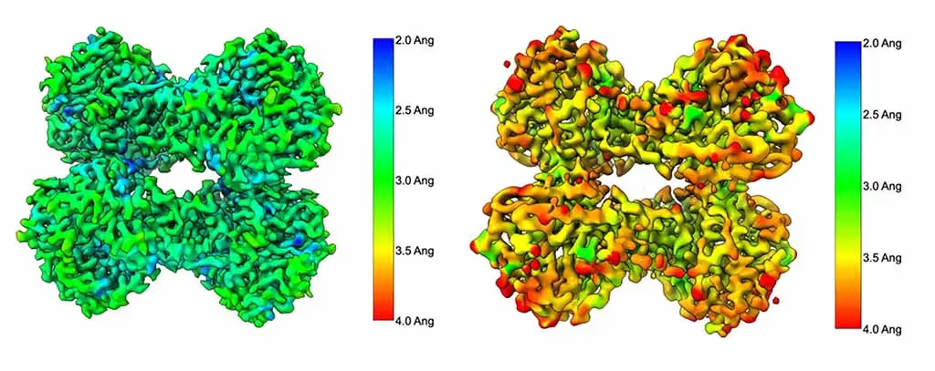
Low concentrations of detergents or other additives can modify protein-interface interactions, but their effects are target-specific. In beta-amylase tests, Tween-20, fluorinated octyl maltoside, octyl glucoside, Cymal-5, fluorinated foscholine 8, and CHAPSO were evaluated. Fluorinated foscholine 8 produced the best view distribution and map quality in that comparison. CHAPSO produced the weakest result and was associated with lower-quality density, particularly in surface-exposed loops.
The local-resolution comparison ranged from approximately 2 to 3 angstroms for fluorinated foscholine 8 and approximately 3.0 to 4.0 angstroms for CHAPSO. Those values describe this beta-amylase experiment. Additive selection should account for protein stability, functional state, buffer compatibility, and the possibility that an additive may improve angular distribution while compromising other structural features.
Continuous carbon and graphene-based support films
Continuous carbon, graphene, and graphene oxide support films can provide a physical surface that competes with the air-water interface for particle adsorption. In the beta-amylase work, continuous carbon and graphene oxide improved the distribution of particle views, but the added support also increased background and reduced signal-to-noise ratio, which lowered overall map quality.
The workflow observations suggest that this tradeoff may be more manageable for particles above approximately 200 kDa. For smaller particles, the loss of signal-to-noise ratio can be more limiting. Treat the mass value as a practical guideline for prioritizing experiments, not an absolute cutoff.
Faster vitrification with the SPT Labtech chameleon
Rapid, blot-free or self-wicking preparation changes the time available for particle diffusion and interface interaction. The chameleon result described above supports this approach as a useful variable when conventional blotting produces a narrow orientation distribution. Grid type, wicking behavior, ice thickness, concentration, and sample stability still require optimization.
Extended and tilted data collection
When less common views are present but undersampled, extending data collection can increase their representation. Faster direct-electron detectors, including the Gatan K3 and TFS Falcon 4 named in the workflow, make larger data sets more practical. If the missing views remain inaccessible at zero tilt, collecting with the grid tilted by approximately 30 to 40 degrees can change the projection geometry and improve angular coverage [3].
Across the project observations summarized here, extended or tilted data collection addressed more than 56 percent of preferred-orientation cases. Tilting introduces tradeoffs: more microscope time, thicker effective ice, lower signal-to-noise ratio, and a potential reduction in attainable resolution. The method may be impractical for very small particles. Gold grids can help limit beam-induced motion, and per-particle contrast transfer function estimation can support processing of tilted data.
A Practical Cryo-EM Sample Preparation Workflow
Confirm the problem. Review two-dimensional class averages, orientation distributions, directional resolution, and whether uncommon views are present at low frequency.
Test the least disruptive chemistry changes first. Evaluate a small detergent or additive panel while monitoring particle integrity and function.
Test an alternate surface when air-water interface adsorption is likely. Compare unsupported ice with continuous carbon, graphene, or graphene oxide while tracking background and signal-to-noise ratio.
Reduce interface exposure time when sample behavior supports it. Compare conventional Vitrobot preparation with a rapid method such as the SPT Labtech chameleon.
Use extended or tilted collection when missing views are present but undersampled. Account for grid stability, ice thickness, particle size, microscope time, and per-particle CTF processing.
Combine methods only after individual tests clarify their effects. A useful combination improves angular coverage without introducing an unacceptable loss of structural detail.
Frequently Asked Questions
What does preferred orientation mean in cryo-EM?
Preferred orientation means that particles in vitreous ice appear in a limited set of views. The imbalance can leave some projection directions underrepresented and reduce the directional information available for three-dimensional reconstruction.
How do you overcome the challenge of preferred particle orientation in cryo-EM?
Potential approaches include changing detergents or additives, using continuous carbon or graphene-based supports, shortening the time between sample deposition and vitrification, extending data collection, tilting the grid, or combining compatible methods. Selection should follow the suspected mechanism and sample behavior.
What are cryo-EM preferred orientation solutions?
The main solution categories are reducing particle interaction with the air-water interface, changing the physical surface encountered by the particles, and collecting data that increases representation of uncommon views. Each category has sample-specific tradeoffs.
How does cryo-EM vitrification affect preferred orientation?
The time between sample deposition and vitrification affects how long particles can diffuse to and interact with the air-water interface. Faster preparation may reduce that opportunity, but the outcome depends on the target, grid, ice, and formulation.
Which sample preparation approaches are best for overcoming common cryo-EM sample prep challenges?
There is no single best method for every target. A practical sequence is to confirm the orientation problem, test limited chemistry changes, evaluate an alternate support or faster vitrification if indicated, and reserve extended or tilted collection for cases where underrepresented views can be recovered.
Can tilting the grid solve preferred orientation in cryo-EM?
Tilting can improve angular coverage when particles remain visible at different projection angles. In the project observations summarized here, extended or tilted collection addressed more than 56 percent of preferred-orientation cases. Particle size, effective ice thickness, signal-to-noise ratio, and beam-induced motion affect suitability.
What is the air-water interface in cryo-EM?
It is the boundary between the thin aqueous sample film and air before vitrification. Protein adsorption at this interface can constrain orientation and may contribute to deformation, denaturation, or dissociation.
Is preferential orientation the same as preferred orientation?
In single-particle cryo-EM, the terms are commonly used for the same sampling problem: particles occupy some orientations much more frequently than others. Orientation bias is another closely related phrase.
Plan a Preferred-Orientation Troubleshooting Study
TrueCourse can help design a focused evaluation of sample chemistry, grid support, vitrification, and data-collection strategies for preferred orientation. Planning should connect each intervention to the suspected mechanism and define the map-quality, angular-coverage, and sample-integrity criteria used to compare conditions.
Peer-reviewed references cited in the draft
[1] Noble, A. J., Dandey, V. P., Wei, H., et al. (2018). Routine single particle CryoEM sample and grid characterization by tomography. eLife, 7, e34257. https://doi.org/10.7554/eLife.34257
[2] D'Imprima, E., Floris, D., Joppe, M., Sánchez, R., Grininger, M., & Kühlbrandt, W. (2019). Protein denaturation at the air-water interface and how to prevent it. eLife, 8, e42747. https://doi.org/10.7554/eLife.42747
[3] Tan, Y. Z., Baldwin, P. R., Davis, J. H., et al. (2017). Addressing preferred specimen orientation in single-particle cryo-EM through tilting. Nature Methods, 14, 793-796. https://doi.org/10.1038/nmeth.4347
[4] Naydenova, K., & Russo, C. J. (2017). Measuring the effects of particle orientation to improve the efficiency of electron cryomicroscopy. Nature Communications, 8, 629. https://doi.org/10.1038/s41467-017-00782-3
.png)
.png)
.png)